History of Freedom LSRV
T
he new Freedom
LSRV design is a follow on to its
sister vehicle concepts the Constitution LSRV and the original Freedom LSRV
featuring the LR99 (X-15 rocket plane engine). The new design rather than hot
rodding a rocket engine we will actually be using a detuned LR-105 rocket engine.
This engine which uses RP-1 (refined Kerosene) and LOX (liquid Oxygen) originally
was  used as the orbital sustainer
or center engine on the Atlas booster which was the United States first ICBM
which went online in the late 1950s.
used as the orbital sustainer
or center engine on the Atlas booster which was the United States first ICBM
which went online in the late 1950s.
The Atlas was also used in the Mercury
manned space program and was the booster used to put America's first astronauts
into orbit. They were astronauts three mice, Enos (a chimpanzee), John Glenn,
and Wally Shirra.
Scott Carpenter and Leroy "Gordo" Cooper. The LR-105 rocket engine
was built by Rocketdyne and was designed to function best at 150,000 plus foot
altitude and would develop better than 80,000 lbs. of thrust. The fuel and
oxidizer were fed into the engine with a turbo pump and the Delaval bell nozzle
was 48 inches in diameter at its exit.
Our engine has been modified by detuning
rather than hot rodding. This is done to get a more reliable and safer engine
thus reducing the chance of malfunction. The LR-105 is one of the most reliable
LOX/Kerosene rocket engines ever built and that is why it was used in the Atlas
ICBM. Detuning has been done by cutting the nozzle down to 20 inches in diameter
and running the fuel and oxidizer into the combustion chamber at half pressure.
The fuel and oxidizer will be fed using a blow down system and a series of
spherical pressure vessels containing inert gasses.  The end results of which
are an engine that is barely putting along at half thrust which is about 40,000
lbs. of thrust (approximately 80,000 horse power at the speed of sound). The
cut down nozzle is to insure proper combustion and flow along
the nozzle walls at about an altitude of 4,000 ft. This is the altitude of
most of the venues we plan to run Freedom LSRV. Ken and I decided this to be
a better solution than "wicking
up" (hot rodding) an already proven engine. What we are doing is taking
a reliable, already proven rocket engine and basically idling it. Later when
greater speeds are required. Stronger, larger propellant tanks can be built,
higher fuel/oxidizer feed pressures will require more pressure vessels to be
added. A composite skirt can be added to the nozzle that will allow future
LSR racers to get the full 80,000 lbs. of thrust if needed.
The end results of which
are an engine that is barely putting along at half thrust which is about 40,000
lbs. of thrust (approximately 80,000 horse power at the speed of sound). The
cut down nozzle is to insure proper combustion and flow along
the nozzle walls at about an altitude of 4,000 ft. This is the altitude of
most of the venues we plan to run Freedom LSRV. Ken and I decided this to be
a better solution than "wicking
up" (hot rodding) an already proven engine. What we are doing is taking
a reliable, already proven rocket engine and basically idling it. Later when
greater speeds are required. Stronger, larger propellant tanks can be built,
higher fuel/oxidizer feed pressures will require more pressure vessels to be
added. A composite skirt can be added to the nozzle that will allow future
LSR racers to get the full 80,000 lbs. of thrust if needed.
I design  all my vehicles to be convertible
in order to be modified as increased speed is needed. The basic concepts are
so well thought out that stability in all axis will only increase with modifications
to increase thrust or duration and the over-all drag will only increase slightly.
Freedom LSRV is designed to be my last effort before I spend my waning years
touring the world and watching what the next generation of LSR racers will
do so Freedom LSRV will be my best effort. Presently I have been helping all
the other teams who are trying to establish a new LSR as much as I can. I don't
consider the other team's competitors but more like brothers who enjoy doing
the same thing I do. This is why I share all my ideas rather than keeping little
secrets. People who keep secrets are insecure in their abilities and know their
best can easily be eclipsed so they live in fear. I have had ideas I give
away freely taken by weenies who claim credit for them. Well, I can't say much
about that except those weenies in their hearts know where "their great
idea" really came from.
all my vehicles to be convertible
in order to be modified as increased speed is needed. The basic concepts are
so well thought out that stability in all axis will only increase with modifications
to increase thrust or duration and the over-all drag will only increase slightly.
Freedom LSRV is designed to be my last effort before I spend my waning years
touring the world and watching what the next generation of LSR racers will
do so Freedom LSRV will be my best effort. Presently I have been helping all
the other teams who are trying to establish a new LSR as much as I can. I don't
consider the other team's competitors but more like brothers who enjoy doing
the same thing I do. This is why I share all my ideas rather than keeping little
secrets. People who keep secrets are insecure in their abilities and know their
best can easily be eclipsed so they live in fear. I have had ideas I give
away freely taken by weenies who claim credit for them. Well, I can't say much
about that except those weenies in their hearts know where "their great
idea" really came from.
The modified LR-105 will give us full
thrust of 40,000 lbs. for 34 seconds with the current propellant tank volumes
we have. The tanks were originally used in a U.S. Army Corporal missile which
was designed to drop a one kiloton nuclear device on an enemy a hundred miles
away. We are using the engine from an Atlas nuclear ICBM and the fuel tanks
from a SRBM or tactical nuclear weapon and
pressure vessels (various diameter titanium spheres) from various satellites
some of which were probably spy satellites to create a car for the peaceful
exploration of speed on the ground. I have always loved the "beating of
swords into plowshares" angle
of unlimited land speed racing. Seems like the incredibly powerful engines
we need to propel our cars at the speeds needed to acquire the LSR today can
only be achieved with components from the most deadly weapons ever devised
by man. Now there is some irony for you!
nuclear ICBM and the fuel tanks
from a SRBM or tactical nuclear weapon and
pressure vessels (various diameter titanium spheres) from various satellites
some of which were probably spy satellites to create a car for the peaceful
exploration of speed on the ground. I have always loved the "beating of
swords into plowshares" angle
of unlimited land speed racing. Seems like the incredibly powerful engines
we need to propel our cars at the speeds needed to acquire the LSR today can
only be achieved with components from the most deadly weapons ever devised
by man. Now there is some irony for you!
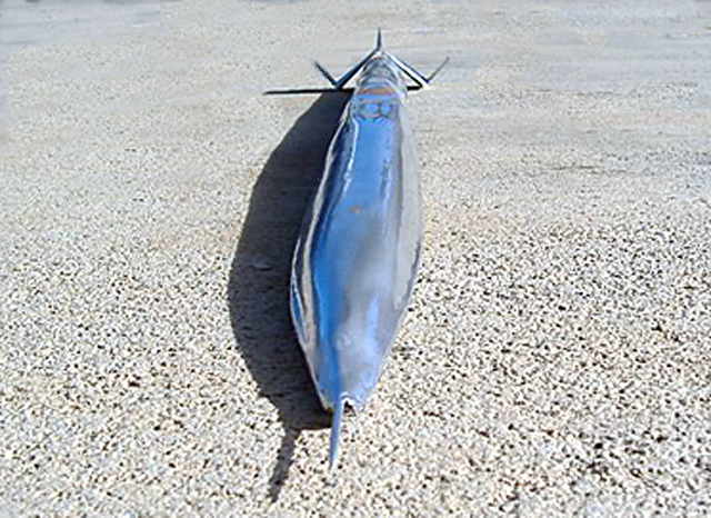
Aerodynamically
Freedom LSRV is the best ground vehicle design I can imagine and the epitome
of 30 years of thought. Unlike the original designs for Constitution and Freedom which used angled wheel spats and large fins
at the rear of the vehicle to produce drag in order to pull the Cp behind the
Cg. My new design will have less drag at the rear even though the surface area
is greater than the other designs. I do this with a flared expanded rear fuselage
as opposed to the straight fuselage with a series of foils at the rear. Most
rocket LSR designs of the past have mimicked a flight rocket in shape which
consists of a pointed nose, a long body ending in a series of fins or foils
to put drag aft of the Cg. The flared rear tail section is a better idea because
it increases drag simply by increasing frontal area at the rear. The larger
tail section is in a shape that will let us control the shock waves rather
than the random interaction and fluctuation of a series of airfoils making
constantly changing shocks. This happens when a supersonic vehicle yaws and
pitches as the vehicle steers and bumps down the course. With a finned rear
tail the drag is usually much higher than can be predicted by calculations
or wind tunnel data because the vehicle is changing attitude ever so slightly
all the time. As this happens shock waves move around and interact adding turbulence
and drag far in excess of what is actually needed thus hurting performance.
So even though the frontal area is greater on the new design than a couple
of wheel spats and airfoils the overall drag will be less and stability will
be achieved at a lesser performance penalty.
which used angled wheel spats and large fins
at the rear of the vehicle to produce drag in order to pull the Cp behind the
Cg. My new design will have less drag at the rear even though the surface area
is greater than the other designs. I do this with a flared expanded rear fuselage
as opposed to the straight fuselage with a series of foils at the rear. Most
rocket LSR designs of the past have mimicked a flight rocket in shape which
consists of a pointed nose, a long body ending in a series of fins or foils
to put drag aft of the Cg. The flared rear tail section is a better idea because
it increases drag simply by increasing frontal area at the rear. The larger
tail section is in a shape that will let us control the shock waves rather
than the random interaction and fluctuation of a series of airfoils making
constantly changing shocks. This happens when a supersonic vehicle yaws and
pitches as the vehicle steers and bumps down the course. With a finned rear
tail the drag is usually much higher than can be predicted by calculations
or wind tunnel data because the vehicle is changing attitude ever so slightly
all the time. As this happens shock waves move around and interact adding turbulence
and drag far in excess of what is actually needed thus hurting performance.
So even though the frontal area is greater on the new design than a couple
of wheel spats and airfoils the overall drag will be less and stability will
be achieved at a lesser performance penalty.
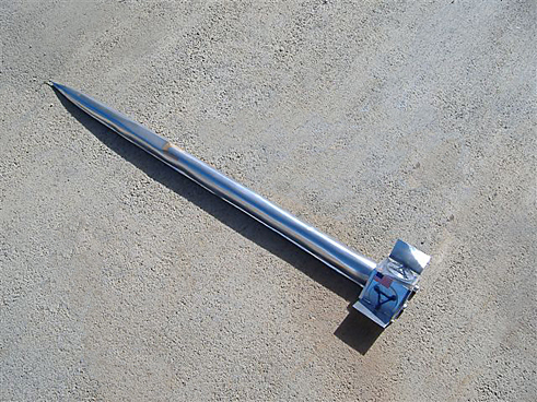
Looking at the front of the vehicle
you will notice that the pitot tube has a long thin airfoil mounted underneath
it. This is a tunable foil used to aerodynamically trim the front of the car.
The long neck of the main fuselage  section starts with a Von Karman
supersonic ogive nose that rises up along the length of the fuselage to about
26 inches tall. Looking at the vehicle from the nose you will notice the bell
shaped fuselage with a flat bottom. This keeps all the air which strikes the
vehicle on top of the vehicle. Because of the bell shape the sides are essentially
the top of the fuselage also. So all the air which strikes the vehicle is felt
on top of the vehicle generating negative lift as a high pressure area there.
This will anchor the long nose of the vehicle to the running surface. Air cannot
get under the vehicle from slipping around and under the edge of the bell lip
because of a 2 inch wide band at the base of the bell running the length of
the vehicle on both sides. When the vehicle goes transonic to supersonic all
the shock generated by the vehicle will radiate above and
section starts with a Von Karman
supersonic ogive nose that rises up along the length of the fuselage to about
26 inches tall. Looking at the vehicle from the nose you will notice the bell
shaped fuselage with a flat bottom. This keeps all the air which strikes the
vehicle on top of the vehicle. Because of the bell shape the sides are essentially
the top of the fuselage also. So all the air which strikes the vehicle is felt
on top of the vehicle generating negative lift as a high pressure area there.
This will anchor the long nose of the vehicle to the running surface. Air cannot
get under the vehicle from slipping around and under the edge of the bell lip
because of a 2 inch wide band at the base of the bell running the length of
the vehicle on both sides. When the vehicle goes transonic to supersonic all
the shock generated by the vehicle will radiate above and  outward from the
vehicle in a horseshoe shape. This wave force will anchor the vehicle
in roll, pitch and yaw. This long thin forward area has a frontal area of 2.9
square feet and a length of approximately 30 feet.
outward from the
vehicle in a horseshoe shape. This wave force will anchor the vehicle
in roll, pitch and yaw. This long thin forward area has a frontal area of 2.9
square feet and a length of approximately 30 feet.
When the air flow goes supersonic
at the flared rear section which has a frontal area of 12 square feet the increased
drag created there will stabilize the vehicle in yaw by acting exactly as a
series of airfoils would. The rear flared section then tapers around the fuel
and oxidizer tanks pulling the air flow into the rocket plume, Because of the
large area of the flared rear section we can hide the rear wheels on either
side of the rocket nozzle. Two composite plates separate the wheels from the
7,500 degree F, 3,000 ft per second rocket exhaust plume and the wheel structures
are mounted on these plates and the rear bulkhead of the car. As the plume
fires it will create a low pressure area against the wheels plates pulling
them towards the plume. The forces being equal on  both plates will keep the
rear wheels from wandering and anchor the vehicle in yaw at the rear.
both plates will keep the
rear wheels from wandering and anchor the vehicle in yaw at the rear.
A large notch above the rocket nozzle
will pull top body air into the plume which will accelerate it reducing base
drag. When the engine cuts out the air in the nozzle notch will become turbulent
and act as sort of a Kamm back. A high drag effect will occur there. This will
add yaw stability once the plume has cut out and help slow the vehicle. There
will also be a large air brake mounted on top of the flared rear section that
will be activated using air cylinders.
Two fins mounted at 45 degrees from
vertical are mounted on booms either side of the rear of the vehicle. These
fins originally came from an Honest John tactical nuclear missile. They are
of bi wedge shape and they are mounted on booms in order to dial in their effectiveness
relative to the Cg. They are canted because when the vehicle goes supersonic
the fins will generate shock waves which will strike the ground and dissipate
away at an angle and  stabilize the vehicle in roll from the rear.
They will also be less prone to weathervaning in a cross wind at this angle.
Shock waves to generate lift of one sort or another is not a new idea. Boeing
used the concept to generate lift on its Mach 3 bomber the XB-70 in the 1960s.
I believe in understanding the forces one will encounter during a project's
operation and using those forces to accomplish the objective. I have said before
it is like a Ju Jitsu expert using his opponent's weight against him.
stabilize the vehicle in roll from the rear.
They will also be less prone to weathervaning in a cross wind at this angle.
Shock waves to generate lift of one sort or another is not a new idea. Boeing
used the concept to generate lift on its Mach 3 bomber the XB-70 in the 1960s.
I believe in understanding the forces one will encounter during a project's
operation and using those forces to accomplish the objective. I have said before
it is like a Ju Jitsu expert using his opponent's weight against him.
To stop the vehicle we will use the
air brake and two high speed supersonic parachutes. Each is 17 foot in diameter
and they will be reefed in order to take the vehicle all the way down the speed
regime to where we can use brakes to stop. I am planning a drag brake similar
to the
type used in Sonic Wind or Craig Breedlove's Spirit of America. I will probably
have a series of air shocks carry the front end off the running surface so
the wheels have full authority. As the vehicle slows to under 100 m.p.h. the
shocks will be bled and a portion of the underside of the vehicle equipped
with a heavy sheet of steel diamond plate will drop and drag the car to a stop.
in order to take the vehicle all the way down the speed
regime to where we can use brakes to stop. I am planning a drag brake similar
to the
type used in Sonic Wind or Craig Breedlove's Spirit of America. I will probably
have a series of air shocks carry the front end off the running surface so
the wheels have full authority. As the vehicle slows to under 100 m.p.h. the
shocks will be bled and a portion of the underside of the vehicle equipped
with a heavy sheet of steel diamond plate will drop and drag the car to a stop.
The wheels on the front will be exactly
the same design I had planned for Constitution and Freedom. A drum with 6 to
eight metal or composite 24" diameter rings running around the outside
of a 20 " diameter
drum. A lubricant will be carried inside the drum and constantly sprayed under
pressure during the run onto the ring wheels. The drum being the entire width of the nose of the car will trip all high speed air flowing behind it causing
a low pressure area down stream under the car. This will help generate negative
lift keeping the nose on the ground. The two rear wheels
will be of the "Skeel" design
I pioneered in the early 1980s which the automotive designer Sbarro is so fond
of taking credit for a decade later they are essentially a large diameter ring
running on an inner race or a space frame with bearings pushed against the
ring wheel with an air cylinder. The purpose of this design is to minimize
internal mass so centrifugal force is reduced and the wheels won't fly apart
at speed.
of the nose of the car will trip all high speed air flowing behind it causing
a low pressure area down stream under the car. This will help generate negative
lift keeping the nose on the ground. The two rear wheels
will be of the "Skeel" design
I pioneered in the early 1980s which the automotive designer Sbarro is so fond
of taking credit for a decade later they are essentially a large diameter ring
running on an inner race or a space frame with bearings pushed against the
ring wheel with an air cylinder. The purpose of this design is to minimize
internal mass so centrifugal force is reduced and the wheels won't fly apart
at speed.
The structure of the vehicle will
be mainly a triangulated, triangular space frame with a few bulkheads and plate
fillets. Mostly built from 2" diameter thick wall mild steel. I originally
wanted to use all stainless steel but driver safety warrants mild steel. The
driver will be encased in a blast proof football shaped cylinder made of Maraging
steel wrapped with a composite fiberglass coating similar to what was done
on Sonic Wind. I will pressurize this capsule in the future. The capsule
will have its own high speed parachute so if an accident occurs the distorting
chassis will spit the capsule away from the vehicle. Anyone who would build
a bi- propellant rocket car and not incorporate such a devise is out of his
mind as big rockets make a big explosion if things get ugly.
The photos enclosed will clear up
all my ramblings. I will update the site more in the future with precise measurements.
Right now I am working out all these. One thing I can tell you for sure is
this vehicle will be unbeatable by the standards of all the new machines being
currently built or planned. Now lets build it!
The "Freedom LSRV" Basic Design Concept
 LSRV stands for
land speed research vehicle. This rocket powered ground vehicle will be capable
of achieving speeds that the official land speed record for automobile contenderswill
not be able to reach for many years if ever, unless this design is copied to
some degree. This new design functions as well aerodynamically in the supersonic
regime as it does in the subsonic speed range. It is one of the first land vehicles
which utilizes varied pressure air and super sonic shock to stabilize the vehicle
in pitch, roll and yaw.In all land speed vehicle designs in the past, the designers
tried to minimize and manipulate the air acting around their land speed vehicle
designs in the hopes of keeping the vehicle moving in a straight line and its'
wheels on the ground. Products of this type of thinking are tall tail fins,
(Which impart an unwanted lifting moment on the vehicle'snose.) canards, (which
develop uneven down force as the vehicle yaws down the course and less or more
of the each canard's area is exposed to the on rushing air.) and tricycle wheel
arrangements. (Which are conducive to rolling over or excessively amplifying
pitching and roll moments on rebound.) All in all because the previous designers
were eitherinfluenced by aircraft or basic automobile design all these concepts
were essentially incorporated design tradeoffs in order to minimize drag and
maintain stability.
LSRV stands for
land speed research vehicle. This rocket powered ground vehicle will be capable
of achieving speeds that the official land speed record for automobile contenderswill
not be able to reach for many years if ever, unless this design is copied to
some degree. This new design functions as well aerodynamically in the supersonic
regime as it does in the subsonic speed range. It is one of the first land vehicles
which utilizes varied pressure air and super sonic shock to stabilize the vehicle
in pitch, roll and yaw.In all land speed vehicle designs in the past, the designers
tried to minimize and manipulate the air acting around their land speed vehicle
designs in the hopes of keeping the vehicle moving in a straight line and its'
wheels on the ground. Products of this type of thinking are tall tail fins,
(Which impart an unwanted lifting moment on the vehicle'snose.) canards, (which
develop uneven down force as the vehicle yaws down the course and less or more
of the each canard's area is exposed to the on rushing air.) and tricycle wheel
arrangements. (Which are conducive to rolling over or excessively amplifying
pitching and roll moments on rebound.) All in all because the previous designers
were eitherinfluenced by aircraft or basic automobile design all these concepts
were essentially incorporated design tradeoffs in order to minimize drag and
maintain stability.
My design philosophy is to first minimize the forces encountered
by the vehicle. This is accomplished aerodynamically by keeping the frontal
area to an absolute minimum at all costs. The idea of concept here is the less
air encountered by the vehicle the less it will be bullied about by that air
(either subsonic or supersonic). It is kind of like being in a fight with many
opponents at one time. It is wiser to move in order to keep your present combatant
in front of you and using his body to block others from reaching you. This way
you essentially fight one opponent a time and have a greater chance of defeating
your adversary. The lesson here is keeping it simple and small to minimize the
forces working against you. I have also incorporated eastern philosophy in using
the aerodynamic forces acting on the vehicle (subsonic and supersonic air flow)
in order to aidin the vehicle's stability and control. Subsonic and supersonic
flow is utilized in this new design to keep the vehicle moving in a straight
line and standing upright. All the fluid forcesacting on this design are totally
incorporated to help it complete its mission just as aJiu Jitsu master uses
his opponent's weight and kinetic energy against him.
 Most previous
LSR designs were aerodynamically "clean" rocket like shapes with various
fins and shrouds added as necessary to stabilize the vehicle. This is evident
in designs like the Blue Flame, SMI Motivato Budweiser Rocket, Spirit of America,
Spirit of America -Sonic Arrow, Thrust SSC and many others. The overall concept
of thinking here is similar to that of an aircraft flying at ground level. The
difference between aircraft and ground vehicles is aircraft, as they move through
the air are constantly adjusting their attitude and altitude. Even flying straight
and level an aircraft is moving slightly up, down, right and left. A ground
vehicle does not have that luxury, as a crash will occur if the vehicle lifts
off or is driven downward even only slightly. A ground vehicle cannot change
its attitude relative to its running surface.
Most previous
LSR designs were aerodynamically "clean" rocket like shapes with various
fins and shrouds added as necessary to stabilize the vehicle. This is evident
in designs like the Blue Flame, SMI Motivato Budweiser Rocket, Spirit of America,
Spirit of America -Sonic Arrow, Thrust SSC and many others. The overall concept
of thinking here is similar to that of an aircraft flying at ground level. The
difference between aircraft and ground vehicles is aircraft, as they move through
the air are constantly adjusting their attitude and altitude. Even flying straight
and level an aircraft is moving slightly up, down, right and left. A ground
vehicle does not have that luxury, as a crash will occur if the vehicle lifts
off or is driven downward even only slightly. A ground vehicle cannot change
its attitude relative to its running surface.
These earlier designs were as light and wispy as the designer could
possibly make them in order to achieve aerodynamic efficiency and make the best
use of available power. They were also made with light aerospace materials like
Aluminum and fiberglass. Keep it as light as possible was the mantra.
These materials have their advantages but they also have many disadvantages.
Metals like Aluminum although light are not conducive to bending and break easily
after only a few cycles of over stress movement. Fiberglass rots in sunlight
and the monocoque concepts using fiberglass lose strength when even slightly
damaged. Composites are fine materials for use in aircraft but not in land speed
cars. I believe a land speed car should be built with more durable materials
such as various grades of Steel and Titanium. Fiberglass is essentially plastic
and plastic decays and rots with time and fatigues easily. Freedom LSRV will
be built to last decades so construction materials have to be robust and maintain
a natural durability. Entropy laws cut no one any slack.
As an example consider the boat or ship. There are still hundreds
of wooden boats built in the 1930s running about on lakes in this country but
you would be pressed to find an old boat built of composites. Near Cairo in
Egypt housed at the base of the pyramid of Cheops. There is a ship on display
that is over 5,000 years old and it still floats. Now try finding operational
fiberglass boats built in the 1950s and 1960s. There are hardly any left and
the reason for that is fiberglass taking a beating on water and left to the
elements will eventually rot and fail. Freedom LSRV will be built small and
stout, with a feeling similar to a steam locomotive or the X-15 rocket research
aircraft. The X-15 was made mostly of Inconel and Inconel X a special steel
designed to withstand high heat and excessive stress.
Rapping on the fuselage or wing of the X-15 your hand strikes
something unmistakably solid with the feel of iron. There is a solidness there
that reminds one of a steam locomotive or a solid block of steel. Small and
built to last is how I would describe the new design for Freedom LSRV. "Built
like a brick out house," as we used to say in the mid west where I grew
up. Most military rocket sleds used for repetitive use are built of mild steel.
Al Teague's "Spirit of 76" LSR streamliner was my inspiration for
Freedom LSRVs' structure. "Spirit of 76" has a very strong chassis
of large diameter, thick wall mild steel tubing that is so rigid it has survived
countless full speed runs at Bonneville in the 25 plus years Teague ran the
car there. Teague took that car to almost every BNI and USFRA meet in all those
years and I am sure not even Al knows how many times he ran that car. Al Teague's
Spirit of 76 was one vehicle built to last!
 In contrast the Blue
Flame although a fantastic design and one of my favorite LSR cars was built
as an Aluminum monocoque. One large dent or tear in the fuselage would render
that car inoperable and in need of a major rebuild. My rocket ice racer Sonic
Wind was based on this type of thinking. It is mainly an Aluminum and fiberglass
composite wrapped driver capsule bolted to a wispy 4130 chromemoly tube space
frame. It is light and although strong in some respects it is very vulnerable.
One damaged area in the monocoque section and the Sonic Wind would be virtually
destroyed.
In contrast the Blue
Flame although a fantastic design and one of my favorite LSR cars was built
as an Aluminum monocoque. One large dent or tear in the fuselage would render
that car inoperable and in need of a major rebuild. My rocket ice racer Sonic
Wind was based on this type of thinking. It is mainly an Aluminum and fiberglass
composite wrapped driver capsule bolted to a wispy 4130 chromemoly tube space
frame. It is light and although strong in some respects it is very vulnerable.
One damaged area in the monocoque section and the Sonic Wind would be virtually
destroyed.
Moncoques although strong as a whole become easily destroyed
once sufficient damage has been sustained. Composite monocoques become dish
rags in crashes when the forces are greater than design limits. Composite (
USAC or Grand Prix ) race cars bleed off energy by shedding parts in a crash.
Consider a modern funny car or dragster, even though the body is made of composites,
the drag racer counts on steel tube to save his life in a crash. This iswhy
ALL dragsters use a space frame built mostly of steel tubing.
I plan to build Freedom LSRV's chassis from 6 and 3 inch diameter
stainless steel tubing. Stainless steel bends in a similar way to mild steel.
Old Bonneville racers built their chassis out of mild steel because they know
that if they get into a crash it is probably going to be a long one because
there are no guard rails to hit and transfer energy to. In a crash at Bonneville
cars simply bounce, spin and tumble bleeding off energy until they finally come
to rest. Chromemoly tubing has spring to it and although it is
the favorite of drag racers because of its strength to weight ratio. It tends
to feed its impact loads into its welds eventually popping welds in a long duration
crash and turning the car into a dish rag. Freedom LSRV's chassis will serve
double duty as chassis and propellant fuel tank. At this time we are planning
to use a mixture of Ethanol and water (the same mixture we use for Sonic Wind)
as the fuel. We have approached many distributors and promoters of Ethanol but
presently none want to help us.
The mega companies promoting Ethanol as the "fuel of the
future" and putting out TV commercials of beautiful children running in
beautiful fields are selling their stock holders pie in the sky in order to
hook potential environmentally concerned investors. These people want you to
believe their companies really care about the environment and will do anything
to help. The truth of the matter is that this world is run by oil money. Most
of the wars fought in the 20th century and most of the wars that will be fought
in the 21st century will be over oil. Many of our presidents were and still
are second and third generation oil men. If you think any major oil corporation
is going to shift their whole operations to a Corn based economy and give up
their mansions, mistresses, drugs and sexual mayhem for cleaner air around the
globe. Contact me because I have a bridge in New York I want to sell you because
you are some kind of dreamer and definitely a sucker. Freedom LSRV's
components will be nestled inside this high strength stainless steel tube framework.
The driver will be in his own tubular capsule built from Maragin steel sheet
and mild steel internal stiffeners with the external skin coated with Teflon.
This driver capsule will be positioned at the center of Gravity of the vehicle
to minimize the G load on him/her during a run. If the vehicle should get into
a crash, it is hoped the driver can survive in this slippery, sliding crash
pod that will contain its own set of parachutes to slow it down.
Freedom LSRV's
components will be nestled inside this high strength stainless steel tube framework.
The driver will be in his own tubular capsule built from Maragin steel sheet
and mild steel internal stiffeners with the external skin coated with Teflon.
This driver capsule will be positioned at the center of Gravity of the vehicle
to minimize the G load on him/her during a run. If the vehicle should get into
a crash, it is hoped the driver can survive in this slippery, sliding crash
pod that will contain its own set of parachutes to slow it down.
The oxidizer for the propellant will be Liquid Oxygen or LOX.
It will be contained in a 24" diameter by 10 foot long tank built of an
exotic stainless steel. The type of material we plan to use is proprietary.
The propellants will be pressure fed or blown into the engine with Helium gas
under high pressure and stored in a number of spherical vessels built of Titanium.
This eliminates the weight and complexity of a turbo pump arrangement. The engine
itself is a LR-99 liquid rocket engine originally developed for the fastest
manned aircraft to date the North American built X-15. This aero spacecraft
reached speeds of in excess of 4,500 M P H and altitudes of greater than 300,000
feet in 1967.
We will be using the original injector mated to a new technology
composite combustion chamber and nozzle. This modification lowers the feed pressures
necessary to pump the propellants into the engine considerably and increases
the over-all performance. 20 to 30 seconds of thrust duration will be needed
for the speeds we envision. A composite combustion chamber will give us at least
twenty full thrust, full duration runs before replacement is necessary. The
original engine combustion chamber and nozzle were formed from hundreds of tubes
which allowed the fuel to flow through them acting as a cooling element before
being fed into the injector for combustion. A composite nozzle/ combustion chamber
although heavier is much more suitable for this project and cools by ablation.
We will use a low and high flow fuel feed circuit. The low flow
will deliver about 15,000 lbs. of thrust while the high flow circuit will deliver
about 35,000 lbs. of thrust. The car will be first run with the low flow circuit
operating and as the car goes super sonic and the drag triples the high flow
circuit will be activated. In the past developing wheels designed to carry a
load and spin at tens of thousands of revolutions per minute were near impossible.
With new techniques and materials available today there are no limits to the
design possibilities. A wheel which is an upset forged "ring" is a
perfect design for land speed applications.
As a motorcycle orstandard automobile wheel such as the Sbarro
wheel designs it is but a novelty but for land speed vehicles it is a Godsend.
I designed ring wheels in the late 1970s for land speed vehicle applications.
We called them "Skeels" back then and the concept's idea was to minimize
internal mass of a spinning wheel. This is perfect for land speed vehicles because
the biggest problem is developing wheels that can handle the tremendous RPMs
needed and not pull themselves apart from centrifugal force.
The front wheels of Freedom LSRV will be a series of 8 rings
24" in outside diameter and 1" wide spinning on a machined drum 22"
in diameter and 12" wide. The drum besides carrying the wheel loads will
carry an automatically ejected lubricant and a cooled liquefied gas probably
Nitrogen. The liquid Nitrogen, will act as lubricant propellant and cooling
element. The idea here is to keep the wheels at a temperature where life is
extended as heat weakens all metals.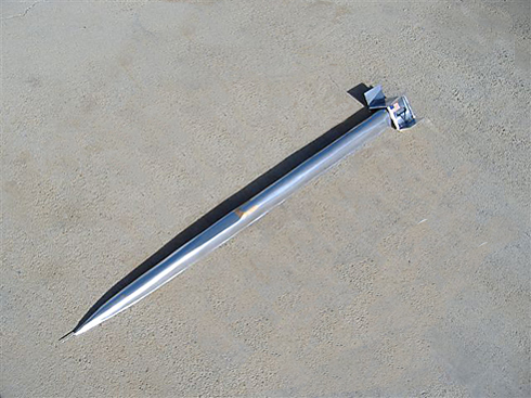 Making the wheels
rings instead of a flat disk on an axle will minimize the internal spinning
mass by simply cutting out the internal material and replacing it with a hub
that does not spin. A disk spinning at high RPM is under a great centrifugal
force and tries to pull itself apart. The drum/ring design carries the spinning
ring wheel loads and acts as a hub and large diameter axle all at once. There
will be two sets of these drum/ring wheels in the nose of the vehicle. One located
just forward of the driver's capsule. This set of wheels will not steer. The
other will be in the extreme nose and will pivot right-left no more than three
degrees. These will be the steering wheels used to control direction. The spinning
masses of both sets of drum/ring wheels will be identical so gyroscopic forces
will be cancelled out as the front set pivots during steering inputs. The rear
wheels use essentially the same concept only on a larger scale.
Making the wheels
rings instead of a flat disk on an axle will minimize the internal spinning
mass by simply cutting out the internal material and replacing it with a hub
that does not spin. A disk spinning at high RPM is under a great centrifugal
force and tries to pull itself apart. The drum/ring design carries the spinning
ring wheel loads and acts as a hub and large diameter axle all at once. There
will be two sets of these drum/ring wheels in the nose of the vehicle. One located
just forward of the driver's capsule. This set of wheels will not steer. The
other will be in the extreme nose and will pivot right-left no more than three
degrees. These will be the steering wheels used to control direction. The spinning
masses of both sets of drum/ring wheels will be identical so gyroscopic forces
will be cancelled out as the front set pivots during steering inputs. The rear
wheels use essentially the same concept only on a larger scale.
The ring wheels envisioned here will be about 4 feet in diameter
and carried on three internal bearings mounted at the three points of an equilateral
triangle. The triangle is a space frame fabricated from 2" diameter thick
wall 4130 Chromemoly tubing. The three bearing themselves mount on the end of
each of three hydraulic bungees inserted into the apex at each angle of the
triangle.
The bungees are all linked together hydraulically so as one is
retracted fluid flows to the other two to force them out picking up the slack.
One point of the triangle is pointed down so that a ground impact forces the
bungee up forcing fluid into the other two bungees forcing them out. The hydraulic
fluid will also be under pressure from an external tank to ensure rebound and
give a pressure or suspension rate that can be controlled. The three bearings
maintain contact in a slot cut into the inside of the ring wheel. Instead of
upset forging these large diameter wheels they will be sliced from a 4' diameter
extruded tube. This will put the metal grain in the right place and although
not perfect is similar to upset forging.
The two rear wheels are mounted so as to be canted 45 degrees inward
at the top. This gives a wide (over 5 Feet) rear track and keeps frontal area
to a minimum. The gyroscopic forces created by the rear canted wheels spinning
provide greater in line stability than that of two wheels mounted side by side.
Two wheels mounted side by side have to be dragged sideways to make a direction
adjustment. The stability advantages are similar to a racing wheelchair only
on a larger scale.
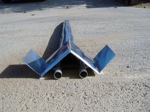
The rear wheels are housed in spats that form a "W"
tail. The purpose of this tail design is to use super sonic shock to stabilize
the vehicle in pitch, roll and yaw. The Wheel spats are linked at the top forming
a triangle. The base of that triangle is welded to two 8" diameter tubes
which extend from the rear of the chassis tubes. These 8" tubes besides
being rear wheel anchor points also house the twin braking parachutes. Because
these tubes extend from the bottom rear of the vehicle, the drag pull felt by
the rear wheels and fin surfaces are felt below and behind the center of gravity
of the vehicle pulling the nose down.
This gives the vehicle straight line stability and a negative
lifting moment at the rear. Supersonic shock created by the top sides of the
W tail play against each other creating a high pressure area over the top of
the W tail. This creates negative lift forcing the tail down. The air under
the tail is blasted away by the 6,100 feet per second rocket exhaust plume.
This creates a low pressure area under the W tail pulling it onto the running
surface.
The outer fins of the W tail generate symmetrical shockwaves that strike the
ground a few feet away from the rear of the tail and exert a pressure against
the ground there. This force acts like an invisible arm holding the rear of
the tail stable in roll against the running surface. The beauty of this idea
is that the shock arm can give stability but has no rebound force back into
the vehicle.
In the current LSR designs such as the Budweiser rocket or the
Blue Flame, the rear wheels are mounted on struts as much as 5 feet from the
centerline of the vehicle. The idea here is to ensure roll stability by giving
a wide rear track. The problem comes when the rear wheel hits a bump or bounces.
The force created by that bouncing wheel is multiplied by the leverage moment
created by the long lever arm distance from the centerline of the vehicle. So
now the wide track works against the vehicle contributing to its want to roll
over. My design eliminates that leverage and rebound moment. Over all aerodynamically
the body uses all the air it encounters to generate negative lift. All the high
speed air is directed over the top of the vehicle. Since the vehicle is Bell
shaped in frontal aspect, the sides and top are essentially the same surface.
When this air becomes super sonic the shock waves are created in a horse shape
over the top of the vehicle anchoring it to the running surface.
The overall nose shape is that of a Von Karman super sonic Ogive.
As the encroaching air reaches supersonic speed a shockwave will form there
anchoring the nose to the running surface. The cockpit lens is a bubble protrusion
just forward of the center of gravity of the vehicle. A shockwave will anchor
there also putting additional pressure on the nose of the car in the same manner
as a set of canard would but without the drag created by canards.
After the air has run the length of the vehicle it is directed
by the canted rear wheel fairing into the rocket plume where it is accelerated
and used to anchor the rear of the vehicle. The skin of the vehicle will be
built from layered up strips of thin sheet stainless that have been scratched
lengthwise along the entire length of the body to vacuum boundary layer air
and keep the skin surface air laminar. The shingle design of the skin gives
any high pressure air trapped under that car a way to escape without exerting
a lifting moment anywhere on the car.
The LOX which is the heaviest expendable in the vehicle is stored
in a tank mounted behind the center of gravity so as it is use the center of
gravity moves forward to increase directional stability. The Ethanol/Water fuel
is stored in the chassis tubes that run throughout the vehicle with the most
of the volume in the 6 inch diameter tubes that make up the base of the chassis.
If the chassis should break or crack the fuel and pressureant gas will vent
out the crack. The fuel pressure will instantly drop and the engine will go
LOX rich and shut down. This could happen even before the driver could react
and shut the engine down manually and is a fail safe idea. If the nose should
lift the driver only needs to shut down the engine and the negative G loads
will slam the Ethanol/ Water fuel forward and down along the chassis tubes forcing
the nose down on the running surface. This is a sort of automatic canard using
principles of physics rather than aerodynamic force. In the case of a total
catastrophic crash my vehicle will rupture at the back of the driver capsule
and spit out the capsule which has its own parachute deceleration package to
slow it down. The major heavy components and the fuel will tumble away from
the capsule reducing the overall mass and the resultant destructive forces.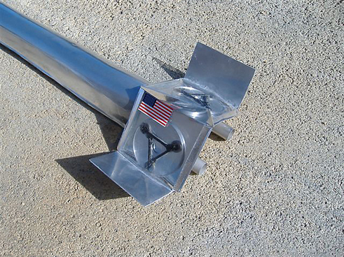 I have always
believed in the capsule concept as opposedto a blast proof roll cage. In a solid
roll cage/chassis design the crash loads are fed back into the chassis of which
the roll cage is a part. So the driver takes a beating inside the roll cage.
An ejection seat is a terrible idea as the decision and action to eject would
take a couple of seconds to perform. By that time the driver could eject himself
right into the ground as the vehicle could already be upside down. If you ever
research LSR crashes as I have you will find that most of the destruction happens
in the first two or three seconds of the crash. After that time the pieces are
only set in motion and scattering about.
I have always
believed in the capsule concept as opposedto a blast proof roll cage. In a solid
roll cage/chassis design the crash loads are fed back into the chassis of which
the roll cage is a part. So the driver takes a beating inside the roll cage.
An ejection seat is a terrible idea as the decision and action to eject would
take a couple of seconds to perform. By that time the driver could eject himself
right into the ground as the vehicle could already be upside down. If you ever
research LSR crashes as I have you will find that most of the destruction happens
in the first two or three seconds of the crash. After that time the pieces are
only set in motion and scattering about.
The driver will be restrained so that only his/her hands can
move. The capsule also places the driver's head at the center of gravity of
the vehicle. In this place the driver is least effected by all the forces he
will encounter no matter what happens. There will be onboard air and a manual/automatic
Halon 2 fire system. A highly visible laser will be mounted in the nose and
functioning during the run. This will be visible in the early morning or late
afternoon when LSR runs are usually made. It is best to run at these times as
winds are generally lower during these times. The Laser will act as an infinite
vehicle length guide to help the driver keep the vehicle in proper alignment.
I plan to take this vehicle up to 1,000 miles per hour personally
to prove concept and capture the land speed record for the United States. After
which it will be left in the Smithsonian in trust so that if the LSR is broken
by another country a younger driver can insure it and take it out and bring
the record back to America. The new driver will also have modification permission
as new technology presents itself. Currently Freedom LSRV is 41 feet long and
has a top speed in the 1,400 MPH regime but with larger/higher pressure tanks
installed and a growth to 57 feet in length. It will be capable of about 2,300
MPH.
After 30 years of thinking and design work by my partner Ken Mason
and myself, this is the best design we can come up with. Ken has come up with
the best ideas in making the LR-99 rocket as efficient and compact as he could
and I have designed the overall vehicle to incorporate ideas I have accumulated
in 30 years of LSR research. I have pulled everything out of my bag of tricks
and have shared them all with you in this design. It is time to start building
this gift to the "Gear heads" and "Rocket heads" of the
world. If anyone has anything better I would love to see it as it would have
to really be something!..........Waldo